EN 61537 for cable tray systems: what engineering firms should check before specifying
Stating in a project that cable trays must comply with EN 61537 is a first step. For that requirement to have technical value, it is also necessary to check which products have been tested, with which accessories, at what support spacing, under which configuration, and which performance values the manufacturer has declared.
In the technical reviews we carry out with engineering firms and installers, we frequently see specifications that mention the standard in general terms but do not include the information needed to compare two cable tray systems. A tray may have the specified width, finish, and price and still fail to perform correctly under the actual load or designed installation configuration.
EN 61537 for cable tray systems turns these decisions into verifiable parameters. It covers requirements and tests relating to mechanical strength, electrical continuity, corrosion, impact, materials, and other system characteristics.
This guide explains what the standard covers, how to interpret technical documentation, and what an engineering firm should check before including a solution in a design report, specification, or bill of quantities.
What EN 61537 is and what it covers
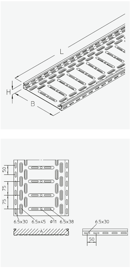
UNE-EN 61537 is the Spanish standard applicable to cable tray systems and cable ladder systems intended to support and accommodate cables in electrical or communication installations.
Its scope includes systems used to:
- Support and route cables.
- Organise different circuits or groups of cables.
- Integrate sections, joints, accessories and support elements.
- Maintain the declared mechanical and electrical performance.
- Facilitate cable installation, maintenance and future extensions.
The standard does not apply to conduit systems, closed electrical distribution trunking or elements intended to conduct current themselves. The current international edition describes the same general scope for cable tray systems and cable ladder systems.
Differences between IEC, EN, UNE-EN and DIN EN
The different designations can cause confusion when an engineering firm receives documentation from several countries.
IEC 61537 is the international standard published by the International Electrotechnical Commission.
EN 61537 is its adoption within the European framework.
UNE-EN 61537 is the Spanish adoption.
DIN EN 61537 is the German adoption and is the reference commonly used in part of the technical documentation issued by PohlCon.
At the time of writing, AENOR lists UNE-EN 61537:2007 as the current standard in Spain, based on IEC 61537:2006. The IEC published a third international edition in 2023, including revisions to corrosion resistance classifications, load test procedures and vertical configurations, among other aspects. Before drafting a specification, it is advisable to verify which edition applies to the project and how it has been adopted in the relevant country.
This point is particularly relevant in international projects. We have encountered cases where the design report cites one designation, the documentation provides another and the product has been assessed against an earlier edition. The references may be compatible, but they must be reviewed and documented.
The standard assesses a system, not an isolated cable tray
One of the most important concepts in EN 61537 is the cable management system.
Final performance does not depend solely on the straight section. It also depends on:
Material and finish. | Profiles and hangers. |
Fixing elements. | Bends and branches. |
Joints between sections. | Ceiling suspension systems. |
Wall brackets and supports. | Distance between support points. |
Reducers and changes in level. | Position of joints relative to supports. |
Covers, when included in the configuration. | |
In our experience, many problems arise when the tray is selected correctly but the support system is left until a later stage. The system changes when the support spacing, bracket type, or joint position is modified.
It is also common for the project to specify one cable tray family while accessories from another source are introduced during procurement. This substitution may make it impossible to demonstrate that the installed configuration matches the tested configuration.
For this reason, the documentation should identify the references included in the test and the installation conditions used. A generic statement of compliance provides less information than documentation linked to a specific family, connectors, and configuration.
Main cable tray tests under EN 61537
The standard addresses different performance characteristics. Not all of them have the same relevance in every installation, but engineering firms need to understand them in order to decide which documentation to request.
Mechanical strength and safe working load
Mechanical strength determines how much weight the system can support while keeping deflection within the established limits.
The documentation may use terms such as:
- SWL.
- Safe working load.
- Safe Working Load.
- Permissible working load.
- SAL, from the German term sichere Arbeitslast.
The declared load depends on variables such as:
Test method. | Cable tray model. |
Load distribution. | Material thickness. |
Width and side height. | Joint position. |
Finish or type of steel. | Support spacing. |
Horizontal or vertical configuration. | |
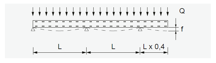
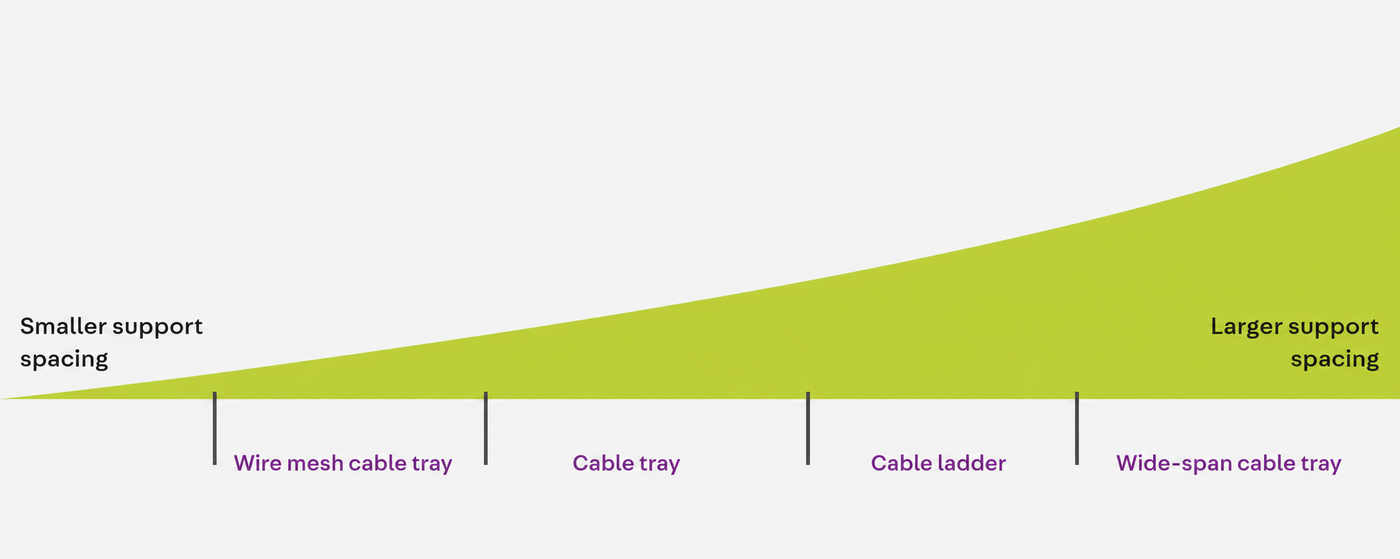
A cable tray does not have a single load capacity that is valid for every installation. As the spacing between supports increases, the permissible distributed load normally decreases and deflection increases.
In PohlCon technical documentation, load tests usually compare different widths, materials, and support spacings. The applied safety factors and the configuration used during testing are also identified.
This information leads to a practical conclusion: knowing the product family is not enough. The engineering firm must match the exact reference to the intended support span.
When we review projects with long routes, we often find two opposing decisions that generate additional costs:
- Selecting an undersized tray and then reducing the support spacing.
- Oversizing trays and brackets without the actual load justifying it.
In the first case, the number of supports, fixings, and installation hours increases. In the second, more steel, weight, and cost are added than necessary. The purpose of the calculation is to find a technically valid and economically proportionate configuration.
Longitudinal and transverse deflection
Mechanical capacity is not assessed solely by checking that the tray does not break.
Deflection under load is also controlled. Excessive deflection can:
- Make maintenance more difficult.
- Hinder future extensions.
- Alter cable distribution.
- Generate stress in joints and accessories.
- Create the impression of a poorly executed installation.
- Reduce the clearance from other building services.
PohlCon planning documentation includes longitudinal and transverse deflection criteria for the tested configurations, together with diagrams that relate load to support spacing. The systems are verified on dedicated test rigs, and the selected scenarios are intended to represent demanding installation conditions.
Load data must be interpreted together with deflection. Comparing two systems solely by the maximum supported weight can lead to an incorrect decision if different deflection limits or test methods have been used.
Tests for supports, brackets and suspension systems
The tray distributes the load, but the supports transfer it to the building structure.
The assessment should include:
- Wall brackets.
- Hangers or vertical supports.
- Ceiling support profiles.
- Double-sided installations.
- Connections between profiles and brackets.
- Fixings to concrete or steel.
- Eccentric loads.
- The distance between the load and the anchoring point.
In real projects, we have found that the support can become the limiting element even when the tray still has sufficient capacity. A long bracket, a fixing close to the edge of the concrete or a load applied on one side only changes the behaviour of the assembly.
PohlCon technical documentation commonly includes checks for brackets, vertical supports and installation configurations, including the deflections and safety margins considered.
The design report should define the tray and the support system as interrelated elements. Leaving open statements such as suitable support according to the manufacturer transfers an important structural decision to the procurement or installation stage.
Impact resistance
During transport, storage and installation, cable trays may be subjected to accidental impacts.
Impact testing checks whether the system retains its performance after a defined mechanical impact. This becomes more important when trays are installed:
- At a low height.
- In maintenance areas.
- In tunnels and technical galleries.
- Near forklift routes.
- In industrial rooms where work is carried out frequently.
- In areas where tools or other objects may fall.
From our on-site experience, localised deformation can affect cover installation, a joint or the usable cable space. Impact resistance should be assessed together with the location and exposure level of the route.
Electrical continuity and equipotential bonding
For metal systems, EN 61537 includes verification of electrical continuity through the tray sections and their joints.
The test verifies that a conductive connection exists between the system elements and that resistance remains within the applicable limits.
PohlCon continuity documentation commonly identifies the evaluated product families, the standard connectors included in the test and the values measured with and without connection elements. This allows the specifier to verify that the performance relates to a defined configuration.
This information demonstrates that continuity has been assessed in a specific configuration. It should not be replaced by an assumption based solely on the tray being made of metal.
Electrical continuity does not automatically mean protective conductor
Three concepts should be distinguished:
- Electrical continuity between components.
- Equipotential bonding of exposed conductive parts.
- Use of the system as a protective conductor.
Passing the continuity test confirms a specific system performance. The decision on earthing and use as a protective conductor must comply with electrical regulations, the project design and the manufacturer’s instructions.
In the enquiries we receive, this distinction prevents many errors. Installing a metal joint does not in itself guarantee that the entire configuration can be used for any electrical function.
Materials and corrosion resistance
EN 61537 includes classifications related to corrosion resistance, but the choice of finish must take the actual environmental conditions into account.
The most common metal solutions include:
- Stainless steel.
- Continuously galvanized steel.
- Other specific surface finishes.
- Hot-dip galvanized steel.
A dry indoor installation does not require the same level of protection as a tunnel, industrial plant, marine area or outdoor route exposed to condensation.
Table 1: Atmospheric corrosivity categories and examples of typical environments
Corrosivity | Unalloyed steel | Unalloyed steel | Zinc | Zinc | Exterior | Interior |
C1 | ≤ 10 | ≤ 1.3 | ≤ 0.7 | ≤ 0.1 | – | Heated buildings with neutral atmospheres. For example, offices, shops, schools and hotels. |
C2 | > 10 to 200 | > 1.3 to 25 | > 0.7 to 5 | > 0.1 to 0.7 | Atmospheres with low pollution levels. Mainly rural areas. | Unheated buildings where condensation may occur. For example, warehouses and sports halls. |
C3 | > 200 to 400 | > 25 to 50 | > 5 to 15 | > 0.7 to 2.1 | Urban and industrial atmospheres with moderate sulphur dioxide pollution; coastal atmospheres with low salinity. | Production areas with high humidity and some air pollution. For example, food-processing plants, laundries, breweries and dairies. |
C4 | > 400 to 650 | > 50 to 80 | > 15 to 30 | > 2.1 to 4.2 | Industrial atmospheres and coastal atmospheres with moderate salinity. | Chemical plants, swimming pools, coastal shipyards and boat harbours. |
C5 | > 650 to 1,500 | > 80 to 200 | > 30 to 60 | > 4.2 to 8.4 | Industrial areas with high humidity and aggressive atmospheres, and coastal atmospheres with high salinity. | Buildings or areas with almost permanent condensation and high pollution. |
CX | > 1,500 to 5,500 | > 200 to 700 | > 60 to 180 | > 8.4 to 25 | Offshore areas with high salinity and industrial areas with extreme humidity and aggressive atmospheres, as well as subtropical and tropical atmospheres. | Industrial areas with extreme humidity and an aggressive atmosphere. |
Source: DIN EN ISO 12944-2:2018-04. Note: the loss values for the corrosivity categories are identical to those in ISO 9223.
When we support an engineering firm at this stage, we pay particular attention to:
- Humidity.
- Temperature.
- Expected service life.
- Condensation.
- Presence of salts.
- Potential chemical agents.
- Industrial contaminants.
- Accessibility for maintenance.
Mechanical compliance with EN 61537 does not replace verification of the coating. For hot-dip galvanized systems, EN ISO 1461 is also relevant and is covered in greater depth in our guide to hot-dip galvanized steel cable trays.
Technical documentation should always identify the material, coating and assessed configuration. This traceability links mechanical or electrical performance to a specific material solution.
Temperature and behaviour in fire conditions
EN 61537 includes requirements relating to materials and their behaviour under certain thermal conditions. For non-metallic components, checks relating to flame propagation may also apply.
This should not be confused with maintaining circuit integrity during a fire.
A cable tray tested to EN 61537 does not automatically achieve an E30, E60 or E90 classification. These performance levels require testing the complete assembly of trays, supports, fixings and cables in accordance with the fire protection standard required for the project.
Confusion often arises in specifications that group several standards under a single expression. The following should be distinguished:
- Reaction to fire of the materials.
- Maintenance of circuit integrity.
- Mechanical strength of the cable tray system.
- Fire resistance of construction elements.
Each performance characteristic requires its own documentation. PohlCon offers specific fire protection solutions that must be assessed independently from general compliance with EN 61537.
How to interpret a load diagram
Load diagrams turn test results into a selection tool.
They usually relate:
- Horizontal axis: support spacing.
- Vertical axis: maximum distributed load.
- Curves: different widths, materials or configurations.
- Additional references: deflection or usable fill volume.
The basic procedure is to locate the intended support spacing and verify the permissible load for the selected family and width.
Fill capacity is not the same as mechanical capacity
A cable tray may have enough space to accommodate a given number of cables but insufficient mechanical capacity to support their weight over the designed span.
Table 2: Space requirements and weight of NYY cables
NYY | Diameter | Space required | Cable weight | Number |
4 x 1.5 | 12.5 | 1.5 | 2.3 | n |
4 x 2.5 | 14.0 | 1.8 | 3.0 | n |
4 x 6 | 16.5 | 3.0 | 5.2 | n |
4 x 16 | 22.0 | 5.0 | 11.0 | n |
4 x 35 | 31.0 | 12.0 | 22.0 | n |
4 x 70 | 41.0 | 16.0 | 41.0 | n |
Conversion: 10 N is approximately equal to 1 kg.
This distinction is critical for:
- Future extensions.
- Power circuits.
- Large cross-section cables.
- Wide cable trays.
- Routes with a high concentration of cables.
- Sections with large spacing between supports.
A situation we frequently encounter is sizing the width by fill capacity and checking the load afterwards. The process should be iterative: fill, weight, span, support, reserve and final validation.
Joint position also matters
Test methods represent specific configurations and place joints at defined positions relative to the supports.
A joint installed at the centre of a span may behave differently from one located near a support. Installation instructions and the test arrangement therefore form part of the information the specifier should review.
PohlCon load documentation commonly includes test diagrams showing supports, joints and measuring points, making it easier to check whether the intended installation reproduces the declared conditions.
A future article will cover load calculation and support spacing in greater detail. For this standards guide, one principle is sufficient: no maximum load should be used without knowing the configuration to which it applies.
Documentation an engineering firm should request
The statement compliant with EN 61537 should be accompanied by documents that make it possible to verify the scope of that compliance.
Before specifying, we recommend requesting:
Test certificate or test report
It should identify:
- Applied standard.
- Edition or reference used.
- Product family.
- Material and finish.
- Accessories included.
- Test method.
- Document date.
- Issuing body or responsible party.
Load tables and diagrams
They should relate:
- Reference.
- Width.
- Material.
- Permissible load.
- Support spacing.
- Deflection.
- Installation configuration.
Electrical continuity information
For metal systems, check:
- Sections assessed.
- Joints used.
- Measured values.
- Permissible limits.
- Applicable clause of the standard.
- Material and coating.
Installation instructions
They should indicate:
- Number and position of joints.
- Fixing elements.
- Tightening torque, where required.
- Maximum support spacing.
- Positioning of supports at bends and branches.
- Treatment of cut edges.
- Installation of covers and accessories.
- Special conditions of use.
Identification of compatible references
Traceability should make it possible to verify that the supplied material matches the documented configuration.
After reviewing different specifications, we have found this to be one of the weakest points. A project may require a tested system, but the purchase order is sometimes written using generic descriptions that allow references to be substituted without verifying equivalence.
Information on manufacturing and its control
Technical documentation may indicate whether the manufacture of the assessed products is subject to controls or surveillance under the relevant test procedure. This information helps link the series-produced product to the documented configuration.
PohlCon brings together catalogues, instructions, certificates and other technical resources in its downloads area. When comparing suppliers, our guide on how to choose a cable tray manufacturer may also be useful.
Common mistakes when specifying cable trays
Selecting a tray solely by its dimensions
Width and height address fill capacity, but they do not define mechanical capacity, corrosion resistance or compatibility with the support system.
For an overview of the main options, see our guide to metal cable trays and our comparison of perforated and unperforated cable trays.
Stating a load without linking it to support spacing
A maximum load without a reference span is incomplete information.
The specification should relate:
- Material.
- Width.
- Distributed load.
- Cable tray family.
- Joint configuration.
- Support spacing.
Applying data from one reference to the entire family
Two trays from the same range may differ in width, thickness or material. The diagram must be checked for the relevant reference or for the expressly included group of references.
Mixing trays, joints and supports from different systems
Dimensional compatibility does not demonstrate mechanical or electrical equivalence.
When components not covered by the same documentation are combined, the engineering firm must justify the performance of the new assembly.
Confusing EN 61537 with a fire protection certification
The cable tray standard does not by itself certify E30, E60 or E90 circuit integrity.
Fire protection requirements must be documented through the specific tests required by the project.
Assuming that any metal joint guarantees continuity
Continuity must be verified with the installed joint and under the conditions declared by the manufacturer.
PohlCon technical documentation distinguishes between measurements on tray sections and configurations with their connectors, enabling the performance of the complete assembly to be checked without relying on assumptions.
Ignoring future loads
Extensions form part of the service life of many installations.
In industrial environments, we have seen routes that were sized for the initial requirement and had no spare capacity only a few years later. The reserve should be defined reasonably, because unjustified excess capacity also increases cost.
EN 61537 checklist before specifying
Before finalising a design report or specification, the following points should be verified:
- Exact cable tray family and reference.
- Width, height and material.
- Current cable weight.
- Reserve planned for future extensions.
- Support spacing.
- Safe working load at that spacing.
- Permissible deflection.
- Joint position.
- Compatible supports and fixings.
- Load and continuity documentation.
- Corrosion classification or protection.
- Installation instructions.
- Independent fire protection requirements.
- Traceability between project, order and installed product.
- Edition of the standard applicable to the project.
This list provides a basis, but each installation may require additional checks relating to vibration, seismic actions, wind, snow, chemical environments or point loads.
How PohlCon documents its cable tray systems
At PohlCon, we assess performance based on the complete system configuration, not an isolated reference.
The technical documentation that commonly accompanies the different product families may include:
Applied standard and test method. | Product material, finish and coating. |
Load diagrams for each configuration. | Installation instructions and planning criteria. |
Identification of the product family and assessed references. | Deflection values and safety factors considered. |
Electrical continuity results with and without connection elements. | List of connectors and accessories included in the assessment. |
Issue date, document owner and validity conditions. | Safe working loads for different widths and support spacings. |
Test diagrams showing the position of supports, joints and measuring points. | |
This form of documentation is particularly useful when the system must be included in a tender, technical specification or engineering review.
As we have seen in projects involving large quantities of trays and supports, an apparently minor decision can be multiplied across hundreds or thousands of units. Validating the load, span, support and finish in advance reduces material changes, oversizing and on-site improvisation.
Frequently asked questions about EN 61537
Is stating compliance with EN 61537 sufficient?
No. The product, tested configuration and performance characteristics relevant to the project must also be identified.
Does the standard define a single support spacing?
No. The manufacturer provides permissible loads for different spacings, references and configurations. The engineering firm selects the appropriate combination.
Is the maximum load the same for every width?
Not necessarily. Geometry, thickness, width and material can alter the system capacity.
Does EN 61537 certify an E90 classification?
No. Maintaining circuit integrity during a fire requires specific tests and documentation.
Does a metal cable tray guarantee electrical continuity?
Continuity must be verified across the assembly formed by the sections and their joints. The fact that the material is metal does not in itself demonstrate the performance of every connection.
Can accessories from different manufacturers be combined?
The combination must be documented or technically justified. Dimensional compatibility does not guarantee that the assembly will retain the tested performance.
Which edition of the standard should an engineering firm cite?
The current and applicable edition must be verified for the country and the project. AENOR currently lists UNE-EN 61537:2007 as the standard in force in Spain, while the latest international edition is IEC 61537:2023.
Data-based specification reduces risk throughout the project
EN 61537 provides a technical framework for comparing cable tray systems using verifiable criteria. It becomes useful when the standard is linked to the reference, load, span, supports, joints, material and installation documentation.
PohlCon Ibérica can help you review these variables and provide the technical documentation required for your project. Our team can analyse the intended configuration, check load diagrams and propose a solution adapted to the environment and actual installation conditions.
Contact our technical team to request documentation and review your cable tray system specification.